
This project, in partnership with the European School of Arts of Britain (l’Ecole Européenne Supérieure d’Arts de Bretagne – EESAB), was carried out under the 2016 Inter-semester FabLab Telecom Bretagne. The group consisted of Maxime BEAU, Lucie MANDRAS, Van Duong NGUYEN, Farah BRAITEH and Change YEE LEONG
Description of the project
This project introduces the concept of “Global Warming” to primary school students in a model that helps them understand the effect of climate changes on icebergs.
Global warming is the gradual increase in the average temperature of the Earth’s atmosphere, a change that is believed to be permanently changing the Earth’s climate, resulting in the melting of icebergs. Since this change is considered as a great humanitarian crisis of our time, it is important to explain the phenomenon of global warming and simulate it in a model. So, students can see how icebergs melt as a result.
Necessary material
To construct the model, the following equipment are needed:
- 1 Arduino
- 4 continous servo 3 SM-S4303R
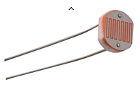
- 3 photoresistors
- Textile, PVC
- Wood
Overview
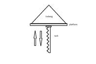
Firstly, three groups of rectangle will be placed under the textile representing the iceberg. A motor is then placed under each group of tubes to either lift the tubes up or set them down. The tubes under the textile, aka the iceberg, will rise to a certain level depending on the intensity of light detected by the photo sensors. Each motor is affected by one photo sensor.
Secondly, a lamp will be used for testing. This lamp emits light, so it represents the increase of temperature in real life. As the light intensity increases, aka the global temperature, the photo sensor will detect a higher light intensity, and the motors will move to set the tubes down, aka the iceberg. By this, the student can understand that the icebergs are melting when the temperature is increasing.
When the lamp is switched off, less light will be detected, and the motors will rotate in the opposite direction to lift the tubes upward. This is important for testing purposes in order to set the model back to its original state, and in cases when the teacher wants to repeat the experiment. Furthermore, the student can understand that when there is no increase in the temperature, the icebergs will remain intact.
The switch will change the state of the lamp: ON/OFF, and the Arduino will control the circuit.
Implementation
The mechanical system is basically a rack and pinon lifting system. We use the pinion of SM-S4303R and use the 3D printer to print the corresponding rack
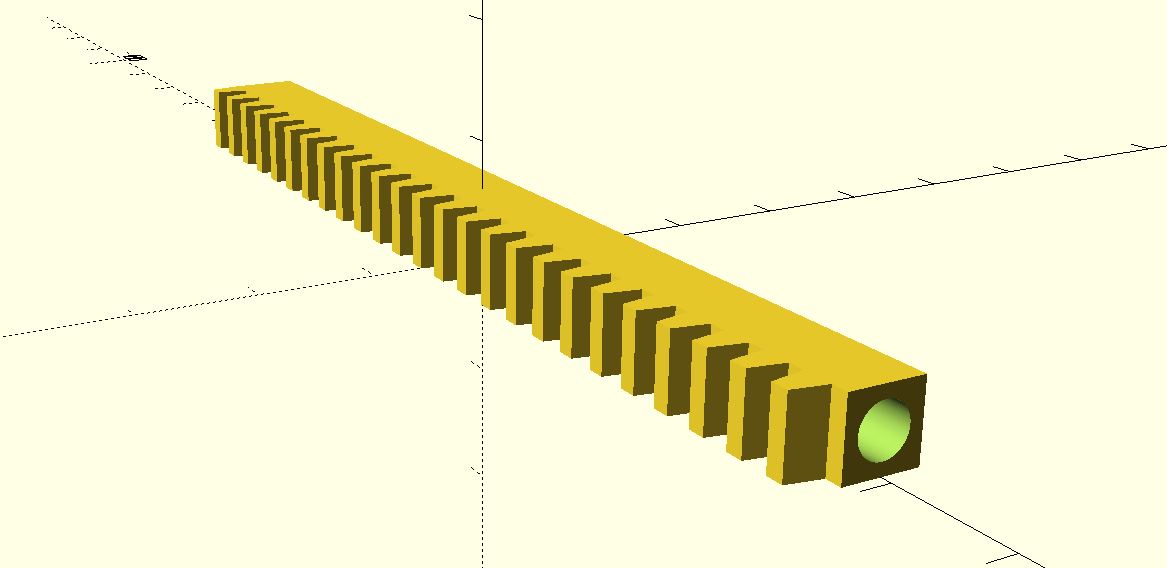
The rack is attached to the platform of iceberg model, which will lift up/down the iceberg model.
The 3 light sensors is set to detect different source of light, the environment/room, and 2 lamps.
As the light sensors detect enough light intensity (pre-set in the embedded code after experimented), the LED will be lighted up. The system is controlled via an Arduino UNO board.
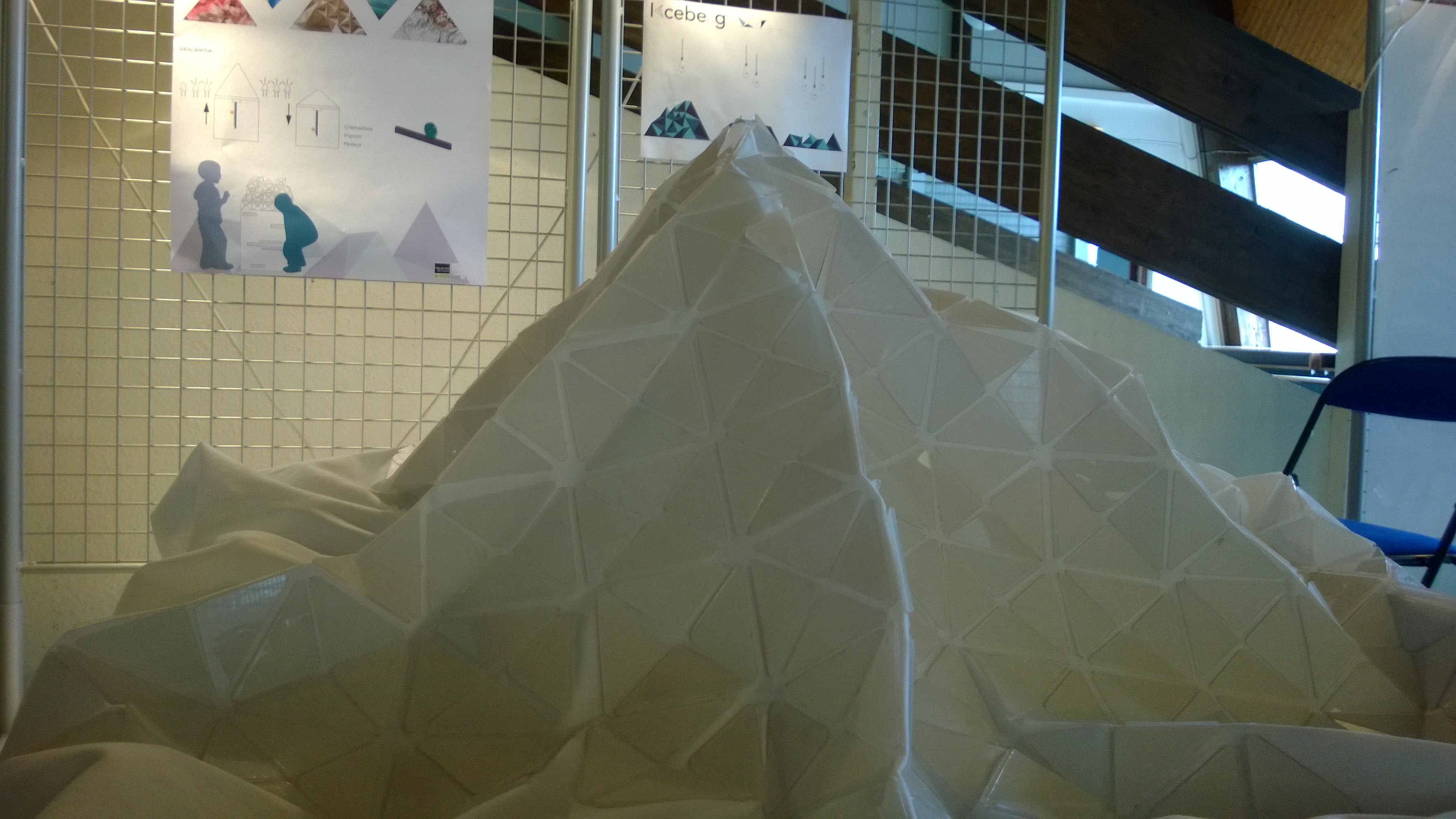
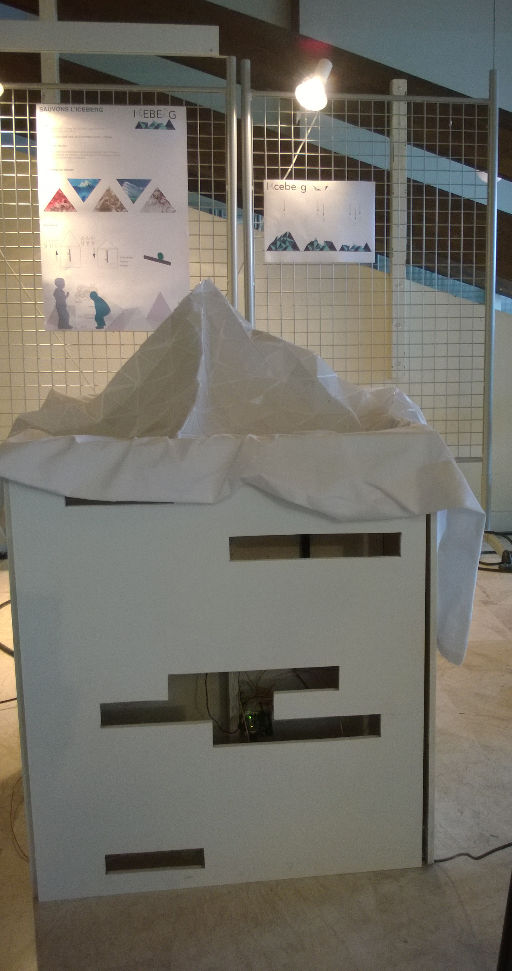
Product
The product of the project is shown in the figure below:
Annexe
Ardruino code:
#include <Servo.h>
Servo myservo1; // create servo object to control a servo
Servo myservo2;
Servo myservo3;
// twelve servo objects can be created on most boardsconst int servo1Up = 30;
const int servo1Down = 150;
const int servo2Up = 150;
const int servo2Down = 20;
const int servo3Up = 150;
const int servo3Down = 30;
const int countThresh = 4;
const int thresh1 = 700;
const int thresh2 = 800;
const int thresh3 = 800;
const int delayTimeUp = 700;
const int delayTimeDown = 500;
const int ledPin = 13;
const int luminosityPin1 = A0;
const int luminosityPin2 = A1;
const int luminosityPin3 = A2;
int pos = 0; // variable to store the servo position
int count1 = 0;
int count2 = 0;
int count3 = 0;
void setup() {
myservo1.attach(9); // attaches the servo on pin 9 to the servo object
myservo2.attach(10);
myservo3.attach(11);
// Initialise la communication avec l’ordinateur
Serial.begin(9600);
// Indique que la broche de la LED est une sortie
pinMode(ledPin, OUTPUT);}
void loop() {
int sensorValue1 =0;
int sensorValue2 =0;
int sensorValue3 =0;
sensorValue1 = analogRead(luminosityPin1);
sensorValue2 = analogRead(luminosityPin2);
sensorValue3 = analogRead(luminosityPin3);
Serial.print(« photo capture1: « );
Serial.print(sensorValue1);
Serial.print(« photo capture2: « );
Serial.print(sensorValue2);
Serial.print(« photo capture3: « );
Serial.print(sensorValue3);
Serial.print(« count: « );
Serial.print(count2);
Serial.print(« \n »);
if ((sensorValue2 > thresh2) && (count2 < countThresh))
{
myservo2.write(servo2Up);
delay(delayTimeUp);
count2 = count2 + 1;
myservo2.write(95);
delay(500);
};
if ((sensorValue2 < thresh2) && (count2 > 0))
{
myservo2.write(servo2Down);
delay(delayTimeDown);
count2 = count2 – 1;
myservo2.write(96);
delay(500);
} ;if ((sensorValue3 > thresh3) && (count3 < countThresh))
{
myservo3.write(servo3Up);
delay(delayTimeUp);
count3 = count3 + 1;
myservo3.write(95);
delay(500);
};
if ((sensorValue3 < thresh3) && (count3 > 0))
{
myservo3.write(servo3Down);
delay(delayTimeDown);
count3 = count3 – 1;
myservo3.write(96);
delay(500);
} ;if ((sensorValue1 > thresh1) && (count1 < countThresh))
{
myservo1.write(servo1Up);
delay(delayTimeUp);
count1 = count1 + 1;
myservo1.write(89);
delay(500);
};
if ((sensorValue1 < thresh1) && (count1 > 0))
{
myservo1.write(servo1Down);
delay(delayTimeDown);
count1 = count1 – 1;
myservo1.write(89);
delay(500);
} ;
}
